Welcome
to the NMBGMR Stick-slip model page
This model was developed by Dave Love at the New Mexico Bureau
of Mines and Mineral Resources. It is simply an extension of the
models developed by FEMA and
Michelle Hall-Wallace (University of Arizona). This model uses
a small motor to pull the brick along the board. Also, instead
of a spring scale attached to the brick, it employs a force sensor
connected to a laptop computer to plot the force exerted on the
brick against time.
List of materials
- Computer
- We used an old 386 laptop and DOS-based software from
Vernier . A high-speed
machine is not necessary.
- Force sensor and serial box plotter
- These, along with the software, were purchased
from Vernier soft- ware
company. The cost for these was about $250
- Board
- We used an eight foot 2x10 inch board purchased from
the local lumber store. This cost about $10.
- Motor
- This is a small motor (cm reversible-gear) that was ordered
from MSC Industrial Supply
Company. The part number is 36690471. The price of
the motor was $55 plus shipping.
- Wooden spool
- A plastic spool that thread
comes on will also work just fine.
- Four conductor wire
- We used a trailer light wiring harness that cost
about $12, but four regular wires will work as long as
you keep them straight as to which is which.
- Two L-shaped brackets
- These came from our local hardware store (ACE Hardware)
and cost about $1.25 each.
- Steel cable
- This is a fine steel cable like the kind used to
hang pictures.
- Switch
- This also came from the hardware store and cost about
$2.50 The switch is a single-pole double-throw switch.
It is used so that we could make the motor turn in both
directions (forward and reverse).
- Project box
- This is a small plastic box available at Radio
Shack for about $2.00. This is what we used to house the
switch so that no bare wires are exposed.
- Three-conductor extension-cord wire
- This also came from the hardware store and cost about
$0.50 per ft. This is used to supply power to the switch.
- Electrical plug
- Also from the hardware store, it cost approximately $2.50.
This was used on the end of the extension cord wire. You
can use a short extension cord and simply cut the female
end off to avoid wiring the plug.
- Small pulley
- This came from the hardware store as well and cost about
$2.00. The pulley wheel is about 5/8" in diameter.
- Wood block: 1x3x3 inches
- This was used to mount the pulley above the board.
This was just wood scrap.
- Assorted springs
- More items from the hardware store. These were under a
dollar each. A variety of springs of different stiffness
can be used to see how each effects the final plot on
the computer. Small S hooks are also very useful.
- Brick or wood block
- I would suggest using a wood block (~ 2x4x8 inches) as
it is easier to drill into and fasten things to. Bricks
can be placed on top of the block for added weight.
- Bracket to connect brick to force sensor.
- 3" T bracket about $1.50 from the hardware store.
This is the reason that I would suggest using a wooden
block rather than a brick. It is much easier to fasten
the bracket to a wood block than to a brick.
- Ring stands and metal rod
- These are used at the motor end of the board so that
the motor is fully suspended. The ring stand came from
our lab and was not purchased for this project.
- 12 inch piece of 2x4" and 18 inch piece of 1x6"
lumber
- These are used to make a foot at the end of the
board so that when the board is level it will sit higher
than the motor and can be secured to the table. The wood
was avialabel scrap.
- Hinges
- These were attached to the foot and the board. These allow
the board to be inclined and still have the foot secured flat
to the table.
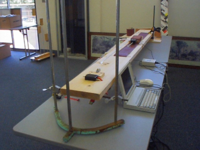
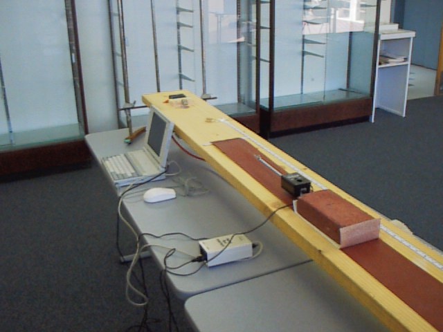
Instructions
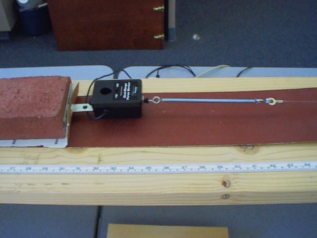
This is what the finial project will look like
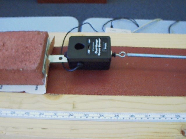
Force meter mount:
- The T bracket will have to be bent in two places. First bend
it at the point where all the arms of the T come together. Then
bend it about an inch and a half lower on the base part of the
T. This will allow the force meter to be screwed to the wooden
block and will keep it from dragging on the sandpaper. Then attach
the force meter to the bracket using the screws that came with
the force meter.
Ramp construction:
Motor mounting:
Start by drilling a 1-inch hole through the 2 x 10 inch board
about 1 foot from the top edge. Then drill a ½ inch hole
about 6 inches from the larger hole (this small hole will be used
to run the wire through). The motor should then be attached to
the L brackets so the legs of the L face out parallel to the motor
shaft (see pictures). The motor and brackets should then be screwed
down to the board with the motor shaft directly over the hole.
The shaft should be perpendicular to the long side of the board.
Be sure to push the wires from the motor through to the other
side so the switch can be wired.
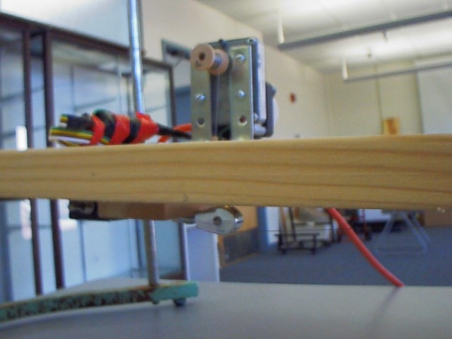
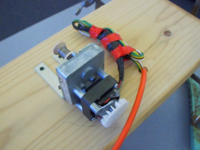 Motor
mounting
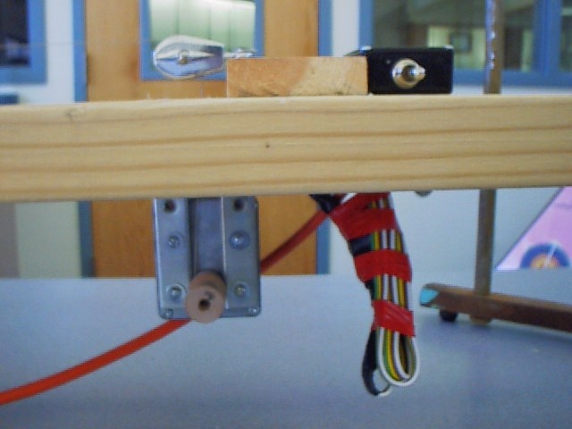
Motor
mounting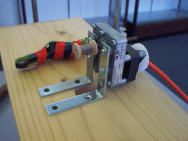
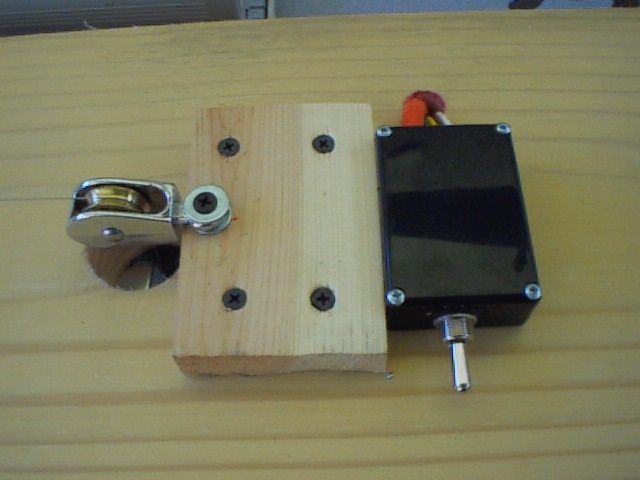
Switch and pulley mounting:
The pulley should be screwed to the small wood block and then
the block should be positioned over the 1-inch hole. After the
block and pulley are lined up with the hole screw down the block.
Then screw the switch box down next to the pulley and wire up
the switch
Wiring the Switch:
All connections made should be
done when the unit is unplugged or
electric shock will occur!!
There will be four wires coming through the ½ inch hole
from the motor and three wires from the power plug. The instructions,
which came with the motor, should be followed very carefully when
the switch and motor are wired.
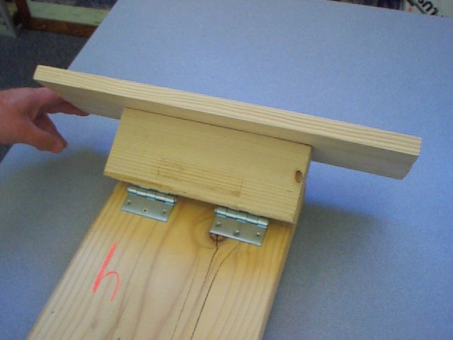
Base hinge mounting:
- First screw the 2 x 4 to the 1 x 6. The 2 x 4 should be centered
on the 1 x 6 for best results. Then mount the hinges to the 2
x 4 about 2 inches from each end. Lastly measure about 6 inches
from the bottom of the ramp and attach the hinges as shown.
Cable and sand paper attachment:
The last task is to drill a small hole (about 1/8 inch ) through
the wooden spool and tie the cable to it. Then put the spool onto
the motor shaft and run the cable through the hole and over the
pulley. Lastly tie the free end of the cable to the eyehook on
the force meter. If springs are being used tie a loop in the cable
and use S hooks to connect the spring to the force meter and cable.
The sandpaper can be attached using Velcro or just double-sided
tape.
- Created By Dave Love, Chris Durand and John Van Der
Kamp
last modified:
25 April, 2022