BOSS MODEL ASSEMBLY
- Cut one of the meter long threaded rods down to 75 cm, leaving
the other full length.
- Cut one of the 61 cm threaded rods down to 45 cm, leaving
the other full length.
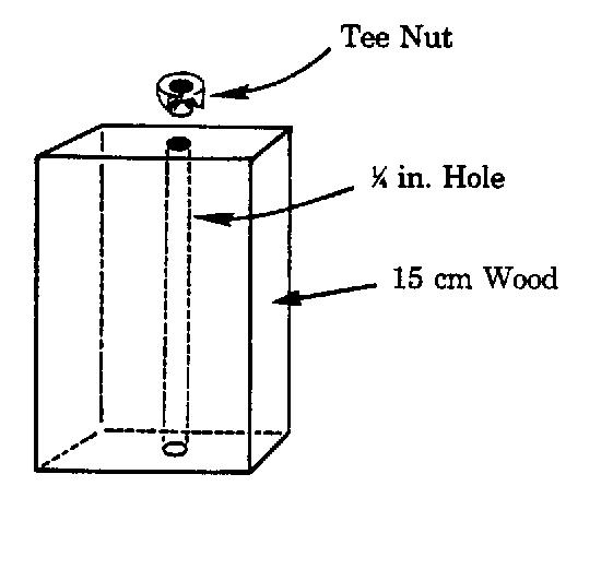
- Drill a 1/4 inch hole through the center of one of the short
sides in each of the 15 cm pieces of wood.
- Hammer a tee nut into the hole on one end of each 15 cm piece.
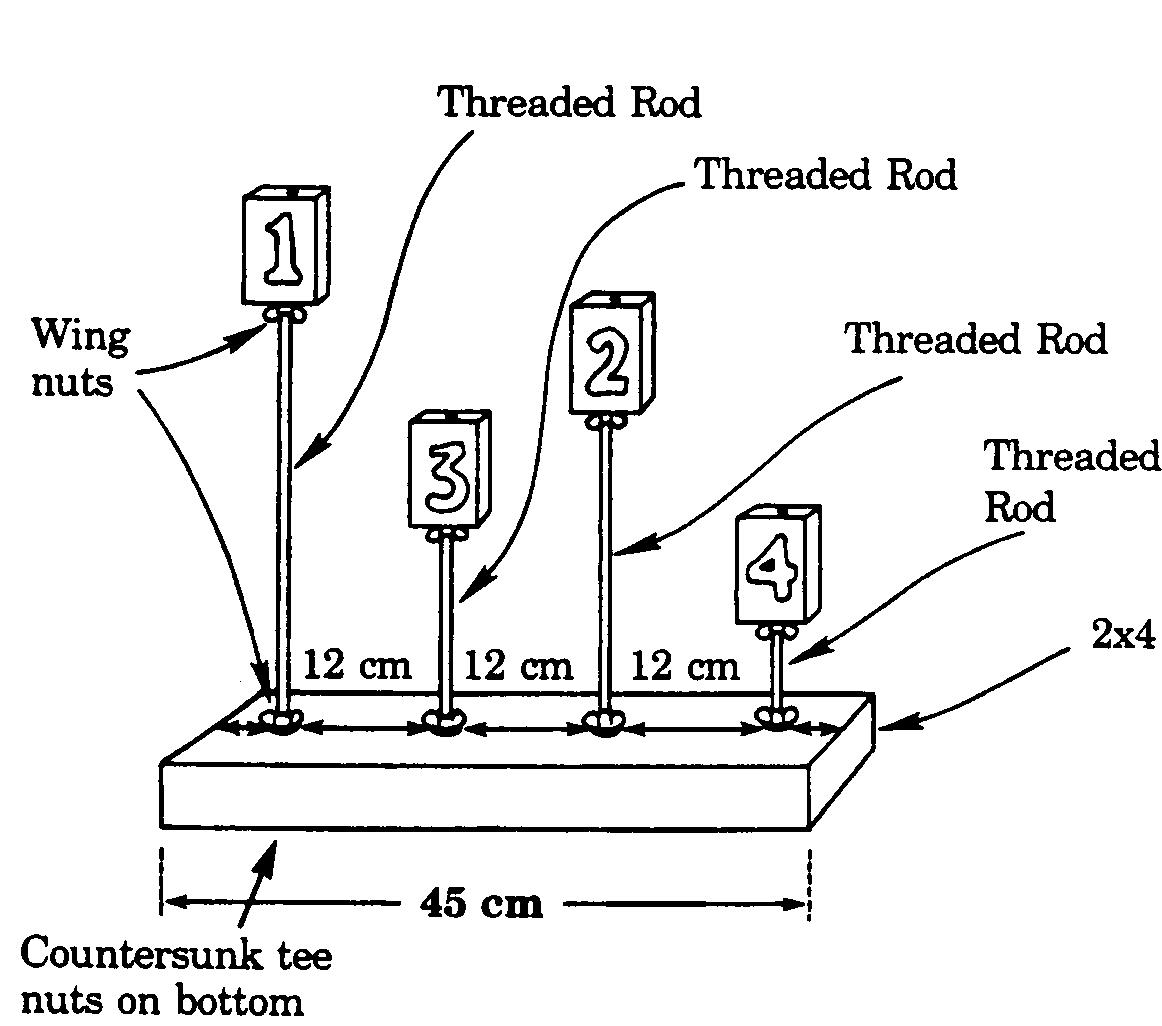
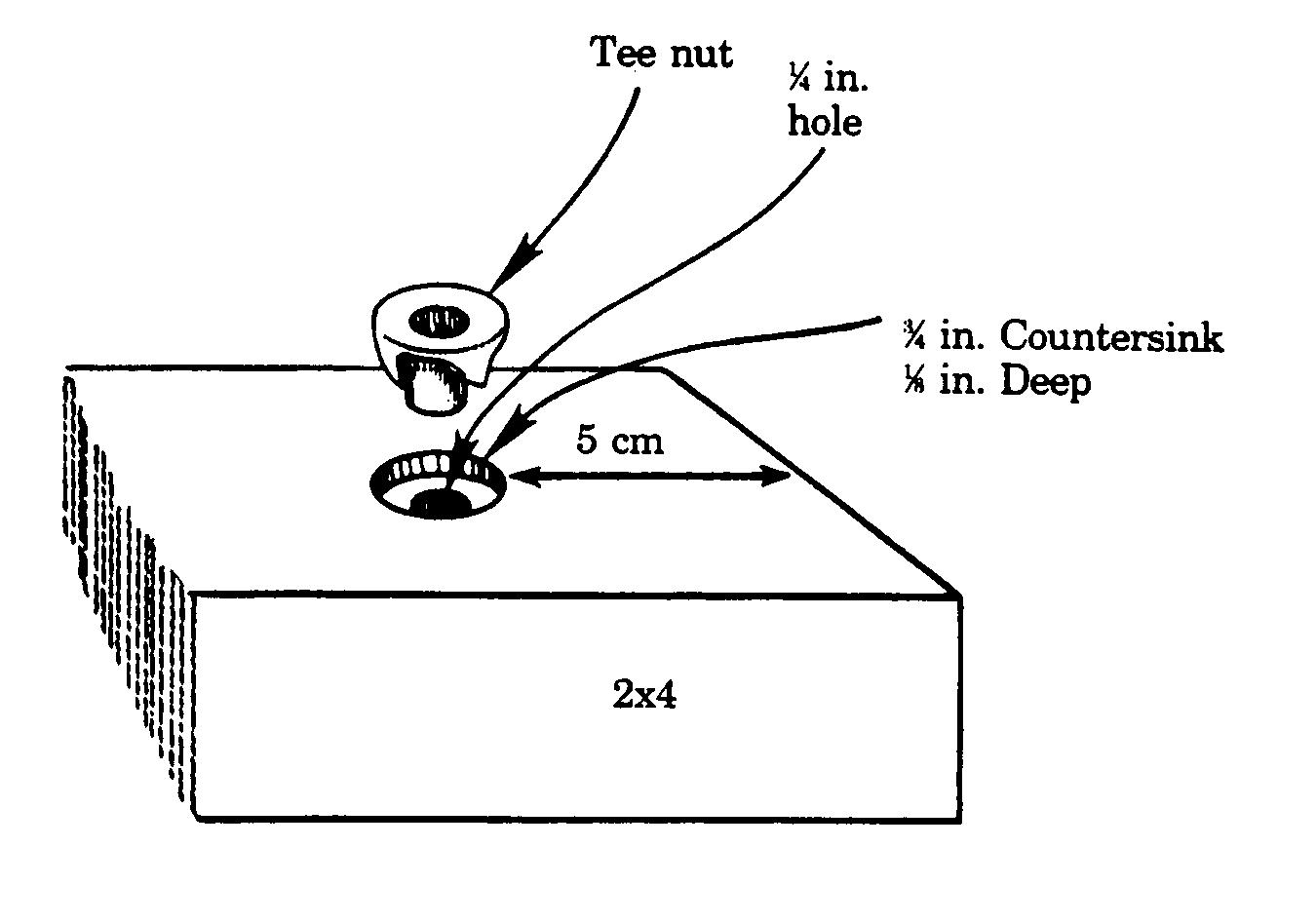
- Countersink four 3/4 inch holes about 1/8 inch deep into
the 45 cm 2 x 4 at 12 cm intervals, as marked on the diagram.
(This will allow you to countersink the nuts so they don't scratch
the surface where the model rests.
- Drill four 1/4 inch holes in the 45 cm 2 x 4 in the counter
sunk holes.
- Hammer a tee nut into each countersunk hole. Turn the
board over so the tee nuts are on the bottom.
- Assemble the rods and the base as shown on the diagram.
- Use the permanent marker to label the 15 cm 1 x 4 inch blocks
in order 1, 2, 3, and 4.
Extensions
This experiment can be run using computer aided software and
sensors for very accurate data collection.
List of materials
- Computer
- We used an old 386 laptop. A high speed machine is not necessary.
- Low G accelerometer, Force sensor and serial box plotter
- These, along with the software,were purchased from Vernier
software company. The cost for these was about $250
- Screws
- Five 3/16 inch x 1 inch screws are used to attach the accelerometer.
Self tapping metal screws are the best and cost about $0.50 at
the hardware store. One will be used to attach the force meter
to the cart.
- Small casters
- Used to make the whole experiment move on the track. Four
1 inch casters will work well. Cost: about $5.
- Angle Iron
- Two three foot pieces of angle iron are used to make a small
track to hold the experiment (The kind with a bunch of holes
drilled in it is the best). The force meter will then be attached
to this and the cart. Cost: about $4.
- Flat strap
- Two 12 inch pieces of flat strap (similar to the angle iron
but flat) are used to hold the angle iron together. Cost:
about $2.
- Bolts
- Four 1/4 inch x 1 inch bolts with nuts and washers to fit
are needed to hold the track together. Three smaller bolts and
nuts will also be needed to attach the force meter to the track
and cart. 3/16 inch x 1/2 inch will do. Cost: about $1.50.
- Brackets
- Four 1 inch L brackets are used to connect the force meter to
the track and cart. Cost: $2.50.
Instructions
This is very easy to construct and will give very accurate
results.
 |
Step 1)
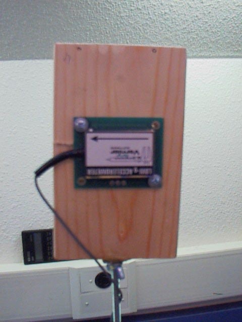
- The accelerometer must be attached to one of the small blocks.
- Place the accelerometer in the middle of the small block
and mark the placement of the holes using a narrow pin or marker.
- Then simply screw the accelerometer down to the block. Be
careful not to tighten it too much or it may break.
|
 |
Step 2)
- This block can then be moved between the different
lengthed rods to collect the data for each trial
- Attach the casters to the bottom of the BOSS model about
1 inch in from each edge.
|
 |
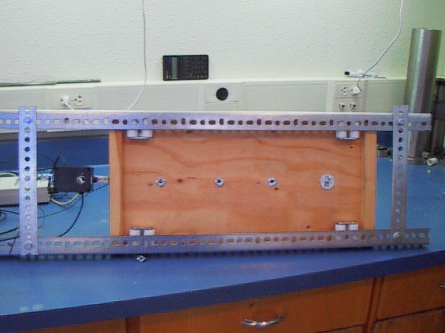
Step 3)
- The angle iron should be attached using the straps and bolts
so that the cart will fit loosely but the wheels should ride
on the angle iron.
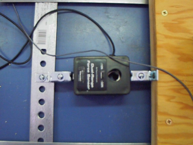
- The L brackets now need to be made into two Z shaped brackets
using the 3/16 inch bolts. One of the Z's will attach to
the force meter
and the track the other should be attached to the force meter
and the cart.
|
Created By Dave Love, Chris Durand and John Van Der
Kamp Last updated 11/13/99
last modified:
25 April, 2022